Motor Testing
In the last few days I prepared the motors and controllers. That means I have attached all the connectors to the wires of motors and controllers so they can be easily plugged together.
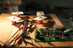
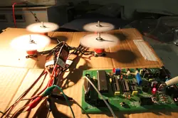
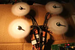
Finally I built a little test setup with all four motors attached to a piece of cardboard. I also attached a piece of paper to each motor to get a bit of air resistance (but I don’t think it resembles the load of real propellers very well :-) ). To be able to set the motor speed, I wrote a little program for my AVR evaluation board which generates the signal for the motor controllers, which was distributed equally to all controllers.
Here are some images of the setup:
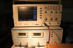
I took these photos at relatively low speed (about 20% according to the signal on the oscilloscope). At full speed, the whole setup draws a current of about 4A, so 1A per motor, which is not that much, as the motors are specified for up to 12A permanent current (15A peak). I guess the current will be much higher with real propellers.
Anyway, I wouldn’t be able to test with much higher load, as my power supply does only provide up to 5A ;-) .
The next step will be a test of the Lisa/M with the motors and the receiver connected, so I will finally see if all the hardware works together.


